
We will discuss an emerging system design technique that has been proven to reduce complex product development costs by 55% [1].
INTRODUCTION & WHY?
As product complexity in virtually every industry has increased exponentially, processes to design and prove device correctness have become more involved. Traditional methods for complex system design in highly regulated industries, such as medical device and aerospace products include the following (simplified) steps1:
1). Manual gathering of requirements
2). Design system and/or architecture
3). Coding and/or development
4). Validation & Verification
Typically the process outlined above is performed in what is referred to as a waterfall approach, in which each of these steps is followed sequentially and fully. Particularly, airborne software standards follow the DO-178C standard and medical software components follow the life cycle processes outlined in IEC 62304.
Suppose during step (4), (validation), a missing requirement is caught. Adding the requirement would require redesign, re-coding, re-verification, and re-validation. This is one reason highly regulated products oftentimes require greater capital investments than consumer electronics.
One seemingly obvious solution is to ensure requirements are fully correct and comprehensive in the early product development stages. In practice, achieving such a feat isn’t always realistic (especially if the product is complex) due to a gamut of reasons including limited foresight, evolving interfaces controlled by external groups, and dynamic regulatory requirements (think General Data Protection Regulation (GDPR)).
Another solution (albeit a poor choice) could be to attempt abridging certain subsets of the process. However, such an endeavor would prove to be haphazard, error-prone, and likely to reduce product quality. An alternative to the above quandary is not necessarily attempting to avoid the process but rather shortening the burden of re-running the steps through automation; Model-Based System Engineering (MBSE) is one such approach.
WHAT IS MODEL BASED SYSTEM ENGINEERING (MBE)?
MBSE is a system design technique that decomposes a system as a representation of simpler elements (via models), connects the models together, and continues to represent complex models in terms of smaller ones. The following terms make up a “system,” as [2] excellently defines:
- Entity are components that make up a system
- Attributes are characteristics of entities, like temperature or volume
- Relationships are associations between attributes and entities based on causality
The key observation is that a system can be broken down hierarchically. So starting with the highest level of abstraction, the top level (system) is designed first and broken into its elements, namely subsystems. The process is repeatedly performed until the lowest level is sufficiently simple and therefore requires no additional decomposition. The definitions of these levels (in progressively greater granularity) are as follow:
- System
- Sub-systems
- Assemblies
- Sub-assemblies
- Parts

HOW TO PUT MBSE INTO PRACTICE?
We can follow a process similar to the formal System Analysis and Design Technique (SADT). Classically, engineers and scientists use these methods by drawing and breaking down the system on a whiteboard or a piece of paper. However, with advances in computer-aided (CAD) modeling, system decomposition can be performed on a computer, using tools, such as CAMEO or MATLAB Simulink. After the design phase is completed, the model is verified, and the code is automatically generated. So, the burden of writing software is significantly reduced.
Consider the impact in time savings. Instead of having to create a 1 million-line program, the vast majority of the coding could be automated. The savings is further underscored when feature enhancements are considered in the development cycle (typically via a change control process). Therefore, effort impacts from required changes are greatly reduced. Faster product cycles (weeks instead of years) becomes possible.
REQUIREMENTS ANALYSIS & GATHERING
For the purposes of this tutorial, we’ll use MATLAB Simulink to design part of a mechanical ventilator medical device. When we start with a medical product, generally we gather product requirements, which include regulatory guidelines. IEC 60601 generally provides additional guidance, such as a required medical device’s alarm volume in decibels and expected operating modes. For this exercise, we will specify a simplified set of requirements, as shown in Fig. 2.

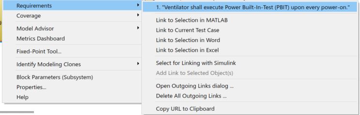
With Simulink modeling, the requirements in Fig. 2 can be linked to the model itself, with the following steps accompanying Fig. 3:
- Open the requirements document in word and highlight the requirements text
- Right-click a specific Simulink block
- Select Requirements
- Select Link to Selection in Word

Fig. 4 shows how to ensure the requirement mapping is successful.
DESIGN INTERFACES & HIGH LEVEL
Let us breaking our system in three main components:
- User Input (Pre)Processor
- Tube & Patient Lung
- Ventilator
- Alarm Subsystem
- Control Micro-controller Unit (MCU) Subsystem
- Pneumatic Subsystem
- Sensors
- Pneumatic Controller
The Ventilator will take user input from the (pre)processor/panel and accordingly adjust the output airflow (for example) to the patient. Inside the ventilator, there is a primary control MCU that controls the Pneumatic Controller, which drives the Pneumatic subsystems (which, in turn, includes sensors and pneumatic components). The alarm subsystem will make a noise and visual indicator if certain fault conditions, such as power loss, are detected.
Consistent with the above, the Simulink Model Browser shows the following:

At the highest level, we design the following interface and major entities comprising the system.

DESIGN LOW LEVELS
Next, we will dig into the yellow box of Fig. 6 and create a Control Logic MCU, Alarm Subsystem, Pneumatic Subsystem, and Pneumatic Controller.

We continually decompose the system until the constituent parts are sufficiently simple and thus no longer divisible. Additionally, the primary control logic implementing the requirements of Fig. 2 is shown in Fig. 8.

For tutorial succinctness, we’ll stop at the third level.
SIMULATION RESULTS
Of course, testing the model is paramount. Testing phases before and after automatic code generation are commonly employed. For now, we will test the model itself. As shown in Fig. 9, the system was able to detect fault conditions when the ventilator was turned off abruptly during ventilation mode (shown visually with the red alarm indicator when the system ON input turned red as well).

By running the simulation while the state machine window is open, the control logic’s state machine can be debugged using Simulink’s Stateflow. The Blue boxes represent the current state machine’s state.
For specific plots pertaining to the patient’s flow, pressure, and volume, Fig. 11 shows the simulated readings from the ventilator’s sensors.

And, we conclude testing with a video showing the readings in live-action.
AUTOMATIC C/C++ CODE GENERATION
As mentioned, a prodigious added benefit of MBSE is automatic code generation, which has saved significant product development costs by ~55% [1]. Code generation is an excellent topic for a future blog article.
NEXT STEPS & ENHANCEMENTS
Verification (and coverage) should be performed as well. An example test includes mathematically integrating the output flow every cycle to ensure the tidal volume is truly delivered to the patient within an error margin. An assertion can be tied to this specific condition for every breathing cycle (often referred in computer science as an invariant).
FOOTER COMMENTARY
1 Implementing a commercial product generally requires several additional steps, such as design reviews. In the context of medical products, risk management processes and quality management processes, for example, need to be in place before, during, and after the product development process. ISO 14971 and ISO 13485 standards, although not directly discussed in this article, would, therefore, be required.
2 Depending on the product’s safety classification (design assurance), the MBSE elements (and the design tool itself) would need to be qualified, which means proven to be developed with a sufficiently high confidence level for meeting the product’s requirements.
REFERENCES
[2] MBSE Primer
ABOUT SIMPLONICS
Simplonics is a leading electronics design consulting and a supplier firm for companies across the United States in highly regulated industries, including medical devices. Our common services include electrical hardware design, software development, and sensor system design.
Our customers tell us horror stories about ex-vendors who delivered defective systems, resulting in safety concerns, vulnerable software, and other issues. We’ve successfully helped companies out of these situations by consistently delivering superior quality and simultaneously reducing recurring costs by more than 20%.
Are you working on a technical challenge and want a fresh perspective? Feel free to reach out by visiting the Contact Us page and submitting your contact information. Let’s build a great relationship for the future.
I am working on same project so Can you please share the module of medical ventilator in simulink or simscape.
Sure – can you provide your email in the contact us page? Thanks.